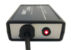
1000 Hz USB TTL Interface
The USB2TTL8 Serial connection can be used to read from, or write to, the 8 TTL data lines using simple text commands. When the USB2TTL8 is in Read Mode, the device can also generate standard keyboard events based on the TTL input state, allowing experiment software to detect changes in the TTL input lines without the need to access the Serial port at all.
Features
Send or receive 8 bit TTL events from any computer with a USB port.
Write 8 bit TTL markers using simple serial commands with under 1 msec latency.
Read 8 bit TTL events as serial messages or standard keyboard events with 1 msec latency.
Control TTL write pulse duration with usec resolution. (Optional)
Works with Windows 7/10/11, Linux, and macOS.
Configure device settings and test device timing using the LabHackers Device Manager application.
Connect to PC parallel port using straight DB25 patch cable (bi-directional data mode supported).
Supported TTL logic levels: 0 - 3.3/5V input; 0 - 3.3V output.
RGB Status LED: Green = Write Mode, Blue = Read Mode, Red = No USB serial connection.


TTL Input Mode
Digital input state can be read using the USB2TTL8 serial interface with one millisecond average latency.
The USB2TTL8 can also be configured to generate standard keyboard events based on the TTL input state. This unique feature allows TTL input events / markers to be detected by experiment software the same way keyboard events are detected. Either a bit level (BITS2KEYS) or byte level (BYTE2KEY) TTL input to keyboard key mapping can be used.
Back to Top
Python Example: Read 8 bit TTL Data Value
import serial
s = serial.Serial('COM3', baudrate=128000, timeout=0.01)
s.write('READ\n')
ttl_data = s.readline()
print("Current TTL State is {}".format(ttl_data))
ttl_data = None
while ttl_data is None:
	ttl_data = s.readline()
print("TTL Event: {}".format(ttl_data))
MatLab Example: Read 8 bit TTL Data Value
% define serial connection
s = serial('COM6','BaudRate', 128000, 'DataBits', 8,'Timeout', 0.01);
% Open port
fopen(s);
% Read current 8 bit TTL value
fprintf(s, 'READ\n');
ttl_data = fscanf(s,'%d');
% Close port
fclose(s);
TTL Output Mode
Using simple serial commands, all eight TTL data lines can be set in parallel or TTL data bits can be set individually.
The TTL output state can also be toggled with usec resolution by providing a usec duration argument to the WRITE command.
Back to Top
Python Example: Set TTL Output to 255 for 5 Milliseconds
import serial, time
s = serial.Serial('COM3', baudrate=128000, timeout=0.01)
s.write('WRITE 255\n')
time.sleep(0.005)
s.write('WRITE 0\n')
s.write('WRITE 255 5000 0\n')
Matlab Example: Set TTL Output to 255 during some operation
%define Serial Port
s = serial('COM6','BaudRate', 128000, 'DataBits', 8);
% Open port for communication
fopen(s)
% write to port
fprintf(s, 'WRITE 255\n');
% insert code to run here
fprintf(s, 'WRITE 0\n');
fprintf(s, 'WRITE 255 5000 0\n');
% close port
fclose(s);
DB25 Pin Out
 Input Pins are 0 - 3.3V (5V tolerant). Output is 0 - 3.3V.
Device Configuration
Set TTL Data Mode: 8 bit Read or Write.
Select whether USB Serial or Keyboard events are generated when in Read mode.
Set TTL input to Keyboard key mappings and maximum key press duration.
Read the serial port address assigned to the USB2TTL8 device.
Set optional Read mode flow control settings.
Test USB2TTL8 USB serial and keyboard event delays.

Options
 |
2 Meter Shielded Male to Male DB25 Cable. (DB25-MM2-EXT) | $30.00 USD |
 |
DB25 Mini M-M Gender Changer. (DB25-MM-GC) | $10.00 USD |
 |
DB25 Screw Terminal Breakout with Case. (DB25-MST-1) | $15.00 USD |
Back to Top
Technical Specifications
| Supported Operating Systems | Windows 11 / 10 / 7, macOS, and Linux |
|---|---|
| Supported Experiment Software | Any software that allows reading and writing to a USB Serial port. |
| USB Connection Type | Full Speed USB 2 Type A (compatible with USB 3)
Use of a USB C port requires a USB C to USB 2 adapter (sold separately). |
| USB Serial Sampling Rate | 1000 Hz (1000 per second) |
| USB Keyboard Event Sampling Rate | 1000 Hz (1000 per second) |
| Serial to TTL Write Latency | 1.0 msec |
| TTL Input Change Event Delay1 | 1.0 msec |
| Internal TTL Input Read Frequency | 150 kHz |
| TTL Input Voltage | 0 - 3.3V (5V tolerant) |
| TTL Output Voltage | 3.3 V |
| USB Serial | Windows 10, 11, and macOS automatically register the USB2TTL8 as a USB Serial device.
Windows 7 requires a USB Serial driver to be installed. Download it thanks to PJRC. Linux needs UDEV rule change. Download it thanks to PJRC. |
| Upgradeable Firmware | Yes, using LabHackers Device Manager Application. |
| Case Size | 91 mm x 66 mm x 28 mm |
| Case Material | ABS Plastic (Black) |
| 1 Computer configuration can impact the ability of your computer to read any USB HID device at 1000 Hz. This can potentially result in increased event latencies (higher mean and stdev). Regardless of the USB Serial or Keyboard device or experiment software being used, it is the experiment software that is responsible for accurately time-stamping events as they are received. | |
